


| le Diagnostic Function | Ignition | Primary Ignition (Voltage) | |
| Primary Ignition(current) | |||
| Primary Ignition(Voltage& Current) | |||
| Primary Ignition (Crankshaft Senser) | |||
| Primary Ignition&SecondaryIgnition | |||
| Secondary | Secondary Ignition Distributor Type (Plug Lead) | ||
| Secondary Ignition Distributor Type (King Lead) | |||
| Secondary DIS (Positive-fired) | |||
| Secondary DIS or CPC (Negative-fired)) | |||
| Secondary Coil Output Diagnosis | |||
| Secondary Ignition&Primary Ignition | |||
| Sensors | Air Flow Meter | Air Flow Meter (Hot Wire) | |
| Air Flow Meter (Air Vane) | |||
| Air FlowSensor (BOSCH Diesel) | |||
| Air Intake PressureSensor (BOSCH Diesel) | |||
| Camshaft | Camshaft (Inductive) | ||
| Camshaft (AC Excited) | |||
| Camshaft (Hall Effect) | |||
| Camshaft (BOSCH Common Rail Diesel) | |||
| Crankshaft | Crankshaft Inductive Running | ||
| Crankshaft Inductive Cranking | |||
| Crankshaft Hall Effect | |||
| Crankshaft Sensor &Primary Ignition | |||
| Distributor | Distributor Pick-up (Hall Effect) | ||
| Distributor Inductive Pick-up Cranking | |||
| Distributor Inductive Pick-up Running | |||
| Lambda Sensors | Lambda Sensor Titania | ||
| Lambda Sensor Zirconia | |||
| Lambda Sensor Zirconia Pre & Post cat | |||
| Throttle Position | Throttle Position Potentiometer | ||
| Throttle Position Switch | |||
| Throttle Pedal Switch (Bosch Diesel) | |||
| ABS Digital Speed Sensor | |||
| ABS Analog Speed Sensor | |||
| Coolant Temperature (5V) | |||
| Coolant Temperature (GM/Vauxhall Simtec | |||
| Crash Sensor | |||
| MAP Analog | |||
| MAP Digital | |||
| Hall Effect Road Speed Sensor | |||
| Accelerator Pedal (Bosch Diesel) | |||
| Bus Diagnosis | CAN Bus | CAN Bus Data View | |
| CAN Bus Signal Integrity | |||
| CAN Bus LH Long Capture | |||
| LIN Bus | LIN Bus | ||
| Engine | Petrol | Single-point Injector (Voltage) | |
| Single-point Injector (Current) | |||
| Multi-point Injector (Voltage) | |||
| Multi-point Injector (Current) | |||
| Injector Voltage & Current | |||
| Injector Current & Primary Ignition | |||
| Diesel | Common Rail Diesel (Current) | ||
| Injector Bosch CDi 3 (Current) | |||
| Injector Bosch Diesel (Idling) | |||
| Injector Bosch Diesel (Accelerating) | |||
| Diesel Glow Plugs | |||
| Electronic Fuel Pump | |||
| Carbon Canister Solenoid Valve | |||
| ERG Recirculation Solenoid Valve | |||
| Stepper Motor Example 1 | |||
| Stepper Motor Example 2 | |||
| Idle Speed Control Valve (Rotary) | |||
| Idle Speed Control Valve (Electromagmetic) | |||
| Throttle Servomotor (Idling) | |||
| Throttle Servomotor (Accelerating) | |||
| Bosch CDi3 Quantity Control Valve | |||
| Bosch CDi3 Pressure Regulator Valve | |||
| Variable-Speed Cooling Fan On | |||
| Variable-Speed Cooling Fan Off | |||
| Variable Camshaft Valve Timing | |||
| Startup & Charge | Charging Circuits | Charging Circuits Current/Voltage | |
| Charging Circuits Current/Voltage Starting 24V | |||
| Charging Circuits Current/Voltage Idling 24V | |||
| Charging Circuits Alternator AC Ripple/Diode Diagnosis | |||
| Relative Compression Petrol | |||
| Relative Compression Diesel | |||
| Starting Voltage Drop | |||
| General Oscilloscope | Model | Hantek1008C | |
| Analog Channel | 8 | ||
| Input Impedance | Resistance: 1MΩ | ||
| Input Sensitivity | 10mV/div to 5V/div | ||
| Input Coupling | DC | ||
| Resolution | 12 bits | ||
| Memory Depth | 4K | ||
| Max. Input | 400V (DC+AC Peak) | ||
| Real-Time Sampling Rate | 2.4MSa/s | ||
| Time BaseRange | 1ns/div to 20000s/div(1-2-5sequences) | ||
| Time Base Precision | ±50ppm | ||
| Trigger Source | CH1, CH2,CH3,CH4, CH5, CH6,CH7,CH8 | ||
| Trigger Mode | Edge | ||
| X-Axis Input | CH1 | ||
| Y-Axis Input | CH2 | ||
| Voltage Measurement | Vpp, Vamp, Vmax, Vmin, Vtop, Vmid, Vbase,Vavg, Vrms, Vcrms, Preshoot, Overshoot | ||
| Time Measurement | Frequency, Period, Rise Time, Fall Time, Positive Width, Negative Width, Duty Cycle | ||
| Cursors Measurement | Horizontal ,Vertical, Track, Auto Measure Modes | ||
| Waveform Signal Process | +,- , x,÷, FFT, Invert | ||
| Voltage Range | 10mV to 5V/div @ x 1 probe | ||
| 100mV to 50V/div @ x 10 probe | |||
| 10V to 5000V/div @ x 1000 probe | |||
| 100V to 50000V/div @ x 10000 probe | |||
| 200mV to 100V/div @ 20:1 | |||
| Current Range | 100mA to50.0A/div @ CC65(20A) | ||
| 1000mA to500.0A/div @ CC65(65A) | |||
| 1A to100.0A/div @ CC650(60A) | |||
| 1A to200.0A/div @CC1100(100A) | |||
| 10A to2000.0A/div @CC1100(1100A) | |||
| FFT | Rectangular, Hanning, Hamming, Blackman Window | ||
| Math | Addition, subtraction, multiplication, division | ||
| Interface | USB 2.0(Full Speed) | ||
| Power | No need extra power supply | ||
| Size | 190 x 167 x 35 (mm) | ||
| Weight | 0.63kg | ||
| High pressure ignition probe | 1 | ||
| Programmablesignal generator | Channel | 8CH | |
| Output Level | LVTTL | ||
| Frequency Range | 0-250kHz | ||
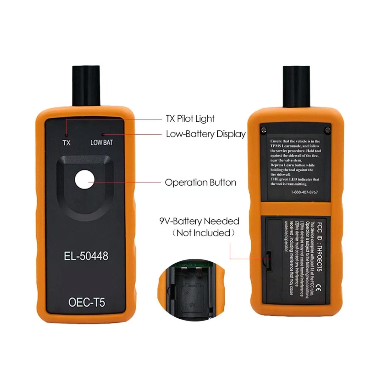
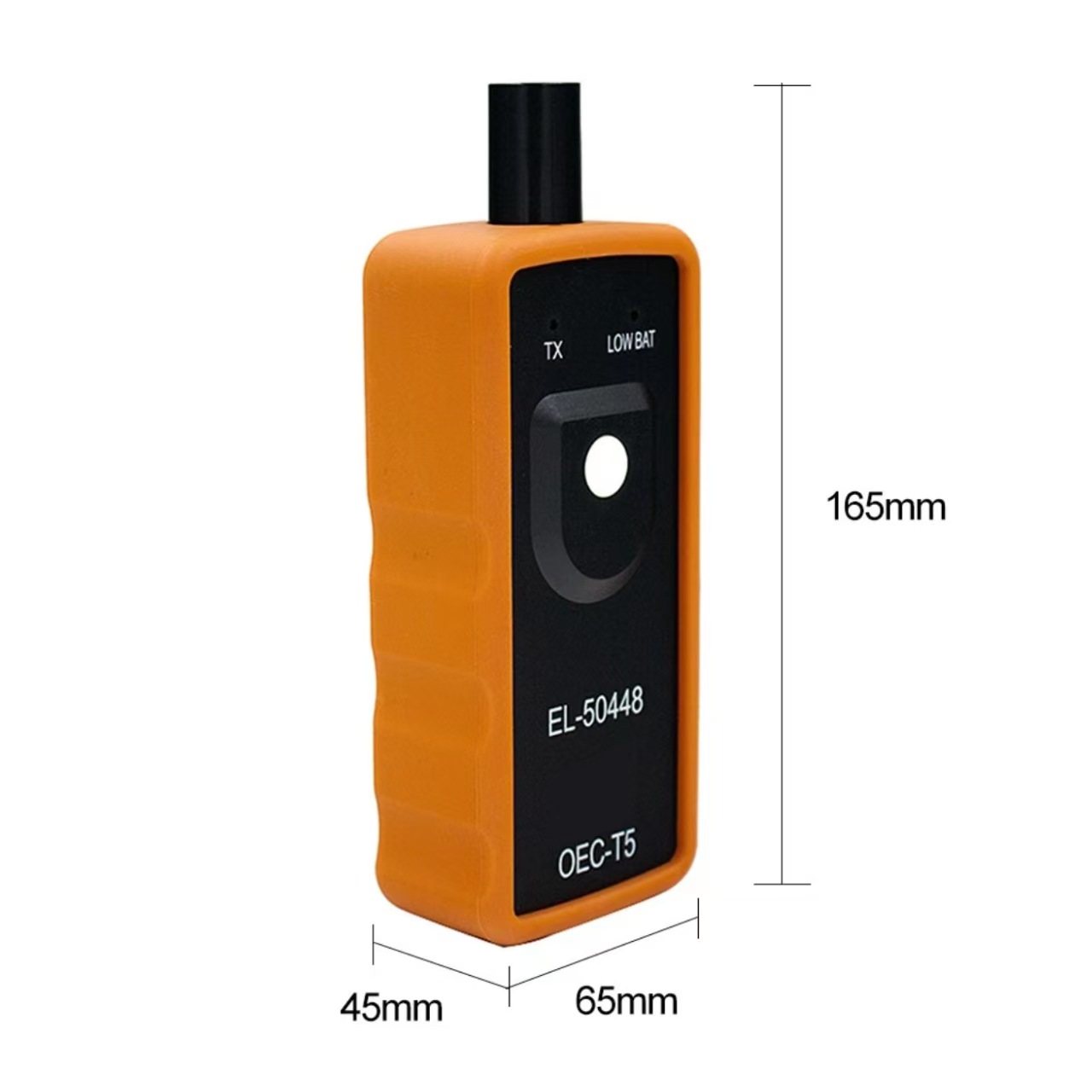
TPMS Relearn Car Auto Reset Tool EL-50448 OEC-T5 Tire Pressure Monitor Sensor
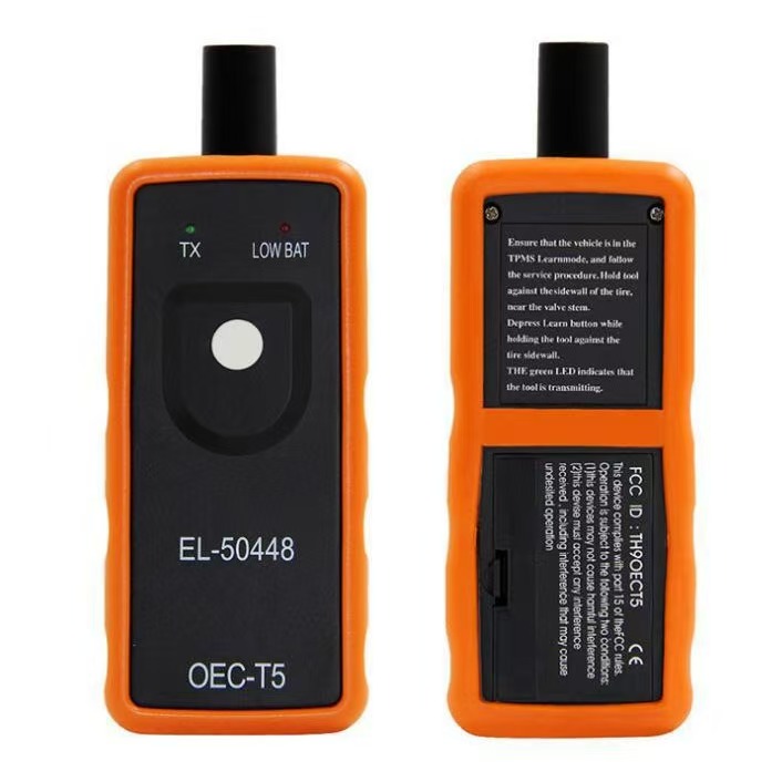 |  |
 |  |
?TPMS Relearn Car Auto Reset Tool EL-50448 OEC-T5 Tire Pressure Monitor Sensor
Description
More Car Lists have been updatedFor GM vehicles equipped with a 315 or 433 MHz Tire Pressure Monitoring (TPM) system, a "Sensor Re-Learn Procedure" must be performed after tire rotations, Remote Control Door Lock Receiver Module replacement or Tire Pressure Sensor replacement. This relearn procedure can be performed by using special tool EL-50448.Also works on 2014 GM models
Orange EL-50448 Tire Pressure Monitor Sensor TPMS Activation Tool OEC-T5
The tire pressure sensor on models in & after 2012 can be read, only with some specified diagnostic tools.Before tire pressure monitoring system works normally properly, the body control module will record ID information of each position in the tire pressure sensor; and use the following methods to read the tire pressure sensor after replacing a tire or wheel speed sensor.
Please refer to the specific methods as follows:
EL-50448 Instructions
EL50448 works on all General Motors (Buick, Cadillac, Chevrolet, GMC) products manufactured for the North American market. It won't work if you've purchased aftermarket sensors that are the wrong frequency. EL50448 fit for G.M most kind of vehicles, equipped with a 315 or 433 MHz Tire Pressure Monitoring (TPM) system. This re-learn procedure can be performed by using special tool EL-50448.
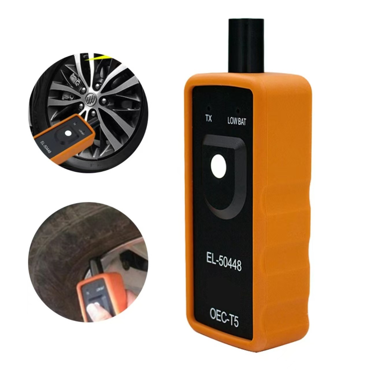
How to use EL 50448 TPMS Activation Tool
Step 1
Enter leaning mode
Set the gearshift lever to "P"
Put the ignition switch to ?ON?
Enter the interface of tire pressure display by DIC
DIC shows "Press Set / Ctrl to re-learn"
Press ?Set / Ctrl?
The turn signal is lighted for 3 seconds and the horn beep sound
twice to enter the learning mode
Step 2
Read tire pressure sensor information
Start from the front-left wheel,