


Product Description
CH341A 24 25 Series EEPROM BIOS Readable And Writable USB Programmer + SOP8 Burning Clip
Product Characteristics
CH341A Programmer:
1. Support for parallel ports: Supports USB printers, EPP, and MEM parallel ports
2. Supported serial ports: Supports USB to UART, I2C, and SP interfaces
3. Output Voltage: There are two options for the output voltage signal level: 3.3V and 5V
4. On-board power indicator light, read/write indicator light, and on-board 506MA resettable fuse
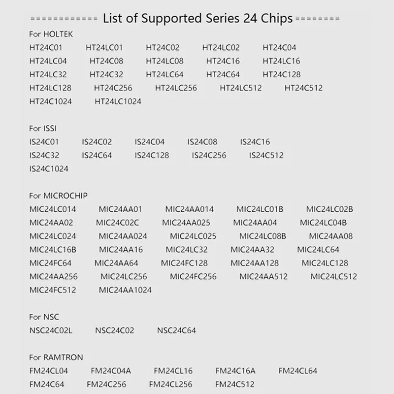
5. Support Series 24 and 25 chips (Read the list below)
6. Supports USB to TTL online flashing (If DuPont cable is required, please purchase it separately)
7. Circuit board with SPI pins corresponding to the MSI JSP11 interface (Special cables are purchased separately)
8. Support for online program download of MCU (for STC) (If you need DuPont cables, please purchase them separately)
9. Provide 5V and 3.3V power outputs. Supports all popular WINDOWS operating systems, including 32-bit and 64-bit systems
Design a 506MA resettable fuse
11. Support 24eerm
12. Stable CH341A chip
13. Support 25spi FLSAH
14. Support the download of MCU programs
15. Support online refreshing
SOP Test Clip With Cable And Adapter Board:
It supports chips with a pitch of 1.27mm, that is, the entire series of SOP8 widths and Sops as narrow as DIP-8.
2. It is applicable to SOP8 chips in 200MIL package and SOP8 chips in 150MIL narrow package.
Usage Method Of The Clamp:
Hold the chip with a clip and apply a 3.3V voltage to the clip pin corresponding to pin 8 of the chip. Generally, a 3.3V power supply has two wires. Then, VCC corresponds to the clamp, and the other wire is directly grounded.
What Should Be Noted When Using Clips Is:
When using the clamp to hold the chip, do not apply force downward. Open the clips and clamp the chip from both the left and right sides. When removing the chip, it cannot be pulled out directly. The clips must be separated from the left and right first, and then removed. In this way, the chuck will basically not be damaged during operation. When encountering a programmer with protection function, the clamp cannot be used under normal voltage. At this time, a voltage of 3.3V needs to be applied.
Product Specification
Condition: 100% Brand New
Material: PCB
Package Included
1 × Programmer
1 × SOP8 Test Clamp With Cable
1 × 8-Pin To 16-Pin Adapter Board
1 × Green Board
2 × 4P Pins
Attention Please
1. Please allow manual measurement errors of 1-5mm. Make sure you don't mind before purchasing.
2. Due to lighting effects, display brightness and contrast Settings, etc., there may be some slight differences in tone between the picture and the actual object. Please make sure you don't mind.