|
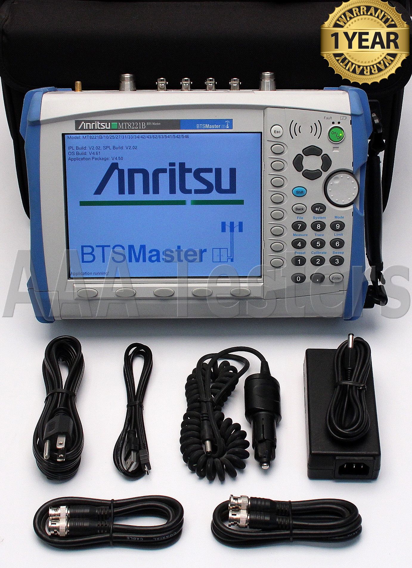
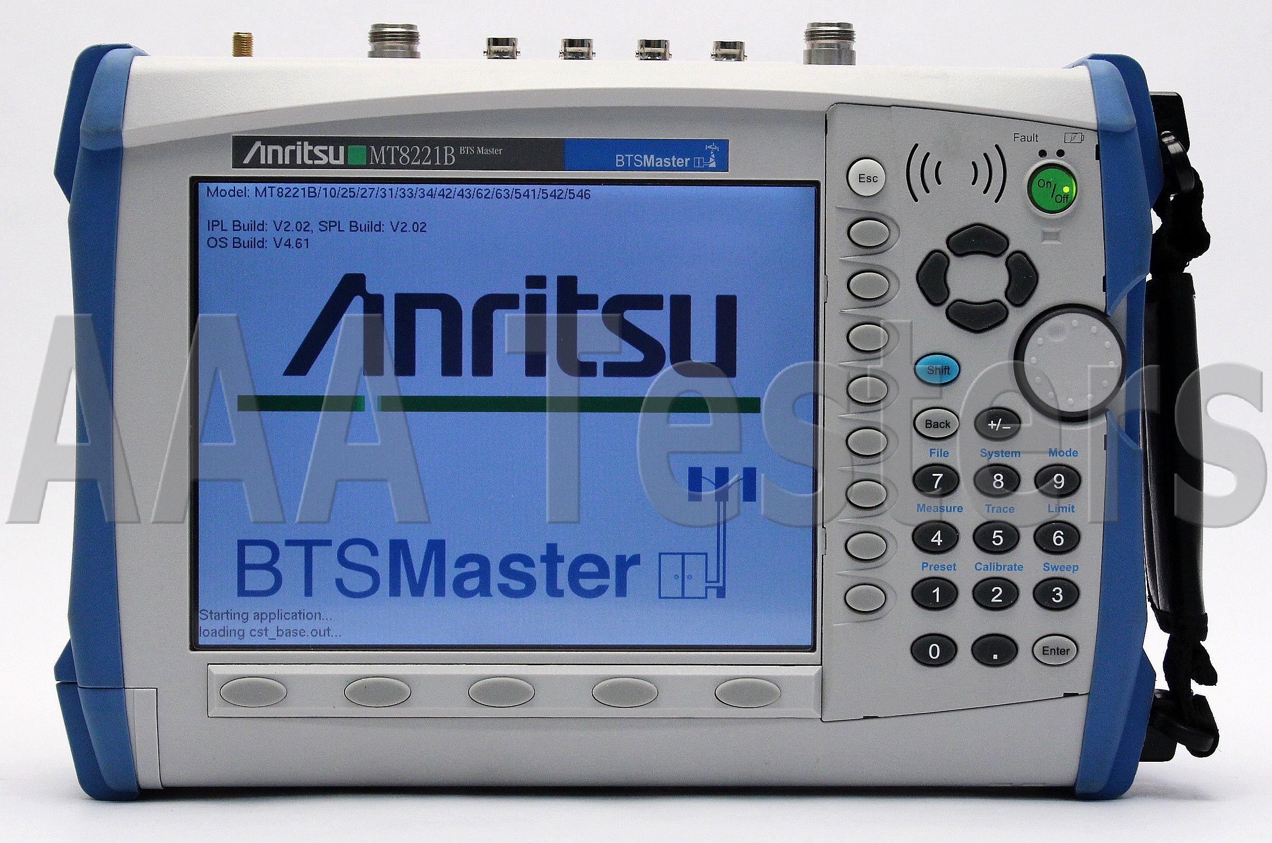
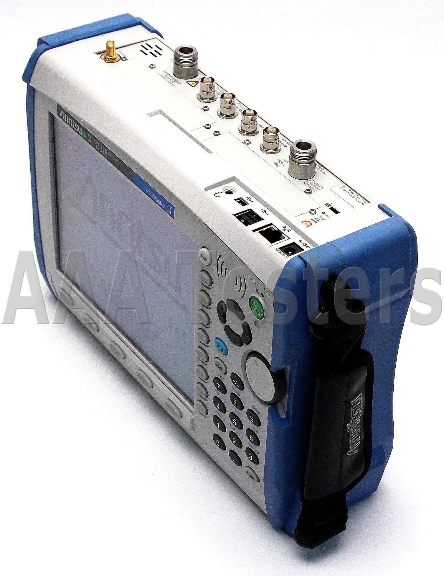
Anritsu MT8221B BTS Master Base Station Analyzer
Cable and Antenna Frequency Range: 400 MHz to 4 GHz
Spectrum Analyzer Frequency Range: 150 kHz to 7.1 GHz
Installed Options:
- Option 10: Bias Tee
- Option 25: Interference Analyzer
- Option 27: Channel Scanner
- Option 31: GPS Receiver
- Option 33: cdmaOne/CDMA2000 1X Over-The-Air Measurements
- Option 34: CDMA2000 1xEV-DO Over-The-Air Measurements
- Option 42: cdmaOne/CDMA2000 1X RF Measurements
- Option 43: cdmaOne/CDMA2000 1X Demodulation
- Option 62: CDMA2000 1xEV-DO RF Measurements
- Option 63: CDMA2000 1xEV-DO Demodulation
- Option 541: LTE RF Measurements (BW - < 10 MHz)
- Option 542: LTE Modulation Measurements (BW - < 10 MHz)
- Option 546: LTE Over-The-Air Measurements
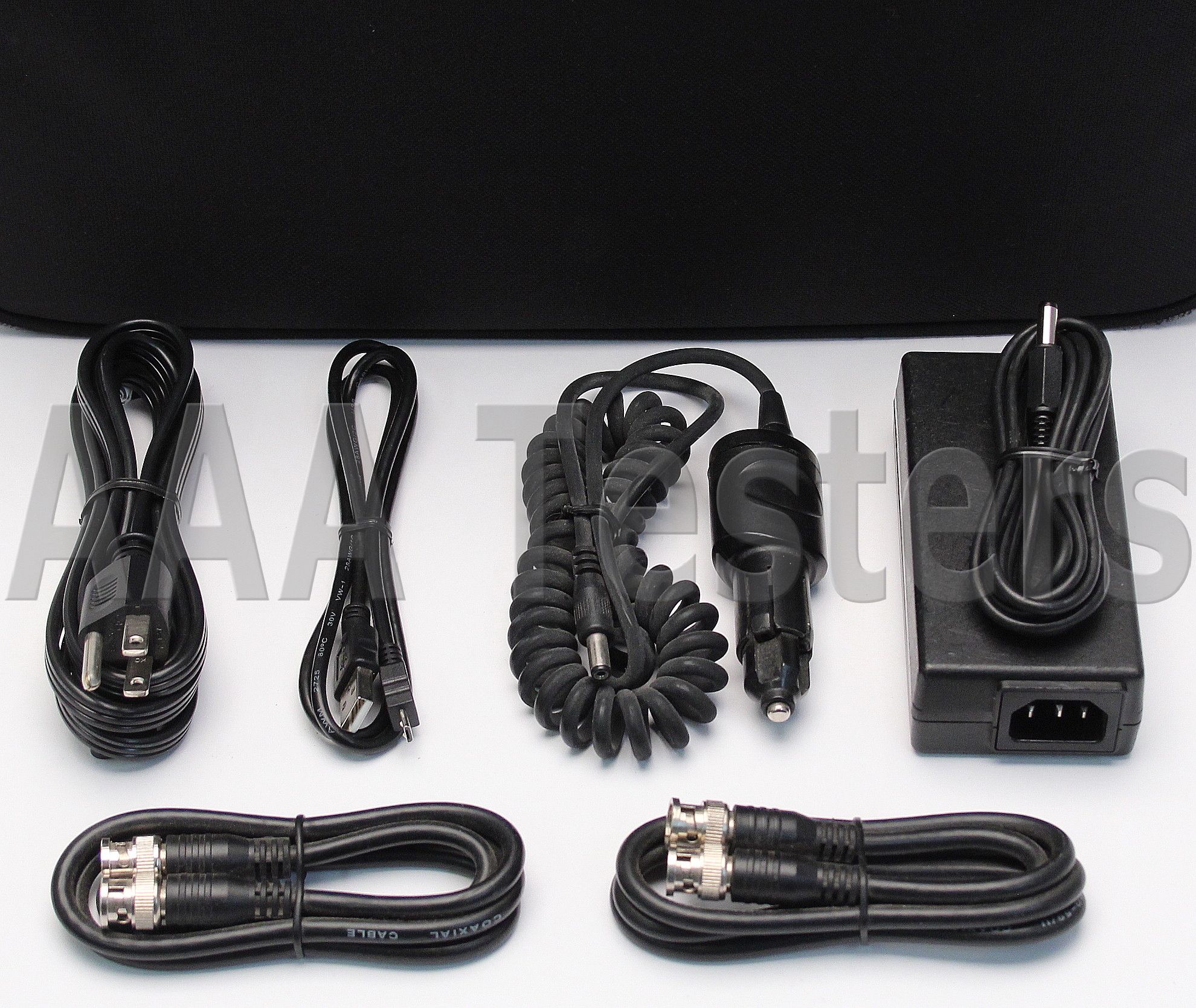
Includes Carrying Case & Accessories As Listed Above!
Working Condition: Excellent
Condition: Refurbished
Calibrated: Yes
Warranty: 1 YEAR WARRANTY
Anritsu MT8221B BTS Master Base Station Analyzer
The BTS Master MT8221B and MT8222B are high-performance handheld base station analyzers that have been specifically developed to support the emerging 4G standards as well as installed 2G, 3G and WiMAX networks. The MT822xB platform introduces:
- 20 MHz LTE modulation quality testing
- Vector Signal Generator (400 MHz to 6 GHz) for comprehensive receiver testing
- 30-MHz Zero-Span IF Output for external demodulation of virtually any other wideband signal
The BTS Master features over 30 analyzers in one to meet virtually every measurement need. Standard features are:
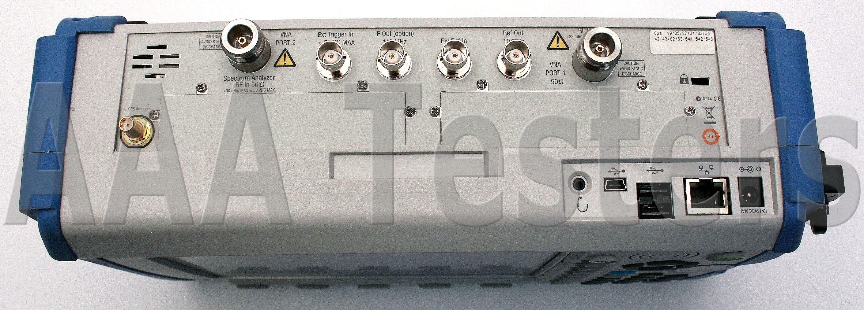
- 2-port Cable and Antenna Analyzer: 400 MHz to 4 GHz
- Spectrum Analyzer: 150 kHz to 7.1 GHz
- Power Meter: 10 MHz to 7.1 GHz
Meeting Key Performance Indicators (KPIs)
Degradation in KPIs, such as dropped call and/or blocked call rates due to a malfunction at the cell site or due to interference, can be easily and accurately diagnosed down to the base station field replaceable unit (FRU) or the offending interfering signal with the BTS Master.
Line Sweep Tools (LST)
LST is a PC program that post processes Antenna, Cable, and PIM traces. It provides a powerful trace analysis and report generator for line sweepers.
Master Software Tools (MST)
MST is a PC program that post processes spectrum analysis traces collected on your instrument. It provides a powerful data analysis tools for spectrum clearing and interference monitoring. With Anritsu’s design know-how and demanding production testing and performance verification you can count on the BTS Master to give you years of reliable dependable service.
Cable and Antenna Analyzer
The BTS Master features 1-port and 2-port Cable and Antenna Analyzer and a PIM Analyzer to be able to test and verify the performance of nearly every feed-line and antenna component. This includes:
- Connectors
- Cables/Jumpers
- Antenna Isolation
- Diplexers/Duplexers
- Tower Mounted Amplifiers
The goal of these measurements is to maximize the coverage, data rate and capacity with problem-free antenna systems minimizing dropped calls and blocked calls for a good customer experience.
Antenna Systems Failure Mechanisms
Maintenance is an on-going requirement as antenna systems’ performance can degrade at any point in time due to:
- Loose connectors
- Improperly weatherized connectors
- Pinched cables
- Poor grounding
- Corroded connectors
- Lightning strikes
- Strong winds misaligning antennas
- Rain getting into cables
- Bullet holes/nails in the cable
- Intermodulation of multiple signals
Making Measurements Easier
The BTS Master provides features for making measurements easier to perform and to analyze test results such as:
- FlexCal eliminates the need to recalibrate when changing frequencies
- High RF Immunity for testing in harsh RF environments
- Trace OVerlay compares reference traces to see changes over time
- Limit Lines and Alarming for providing reference standards
- High Power output to test tower-top components without climbing the tower
- Internal Bias-Tee to power up TMAs for testing when off-line
- GPS tagging of data to verify location of tests
- Line Sweep Tools for post-analysis and report generation
Spectrum Analyzer
The BTS Master features the most powerful handheld spectrum analyzer for field use with unmatched performance such as:
- Sensitivity
- Dynamic Range
- Phase Noise
- Frequency Accuracy
- Resolution Bandwidth (RBW)
The goal of the Spectrum Analyzer’s measurements is to be able to monitor, measure, and analyze RF signals and their environments. It finds rogue signals, measures carriers and distortion, and verifies base stations’ signal performance. It validates carrier frequency and identifies desired and undesired signals.
Simple But Powerful
The BTS Master features dedicated routines for one-button measurements and for more in-depth analysis the technician has control over the setting and features not even found on lab-grade benchtop spectrum analyzers, for instance:
- Multiple sweep detection methods - true RMS detector, quasipeak, ...
- Multiple traces and control - three traces, trace math, ...
- Advanced marker function - noise marker, frequency counter, ...
- Advanced limit line functions - one-button envelope creation, relative, ...
- Save-on-Event - auotmatically saves a sweep when crossing a limit line
- Gated sweep - view pulsed or burst signals only when they are on, or off
- I/Q waveform capture - transfer captured signals for further analysis and troubleshooting
Power Meters
The BTS Master offers as standard a builtin Power Meter utilizing the Spectrum Analyzer and an optional High Accuracy Power Meter requiring external power sensors.
Setting the transmitter output power of a base station properly is critical to the overall operation of a wireless network. A 1.5 dB change in power levels means a 15% change in coverage area.
Too much power means overlapping coverage which translates into cell-tocell self interference. Too little power, too little coverage, creates island cells with non-overlapping cell sites and reduced in-building coverage. High or low values will cause dead zones/dropped calls, lower data rates/reduced capacity near cell edges, and cell loading imbalances/blocked calls.
Specifications:
| Cable and Antenna Analyzer |
| Measurements |
VSWR, Return Loss, Cable Loss, Distance-to-Fault (DTF) VSWR, Distance-to-Fault (DTF) Return Loss, 1-port Phase, 2-port Phase, 2-port Gain, Smith Chart |
| Setup Parameters |
| Frequency |
Start/Stop, Signal Standard, Start Cal |
DTF
|
Start/Stop, DTF Aid, Units (m/ft), Cable Loss, Propagation Velocity, Cable, Windowing |
Windowing
|
Rectangular, Normal Side Lobe, Low Side Lobe, Minimum Side Lobe |
Amplitude
|
Top, Bottom Auto Scale, Full Scale |
Sweep
|
Run/Hold, Single/Continuous, RF Immunity (High/Low), Data Points, Averaging/Smoothing, Output Power (High/Low) |
Data Points
|
137, 275, 551 |
Markers
|
Markers 1 to 6 each with a Delta Marker, Marker to Peak/Valley, Marker Table (On/Off), All Markers Off |
Traces
|
Recall, Copy to Display Memory, No Trace Math, Trace + Memory, Trace - Memory, Trace Overlay (On/Off) |
Limit Line
|
On/Off, Single Limit, Multi-segment (41), Limit Alarm, Clear |
Limit Line Edit
|
Frequency, Amplitude, Add Point, Delete Point, Next Point Left, Next Point Right, Move Limit |
Calibration
|
Start Cal, 1/2-port, Low/High Power, Standard/FlexCal™, DUT Connector, Configure DUT |
Save/Recall
|
Setups, Measurements, Screen Shots (JPEG - save only) |
Application Options
|
Bias-Tee (On/Off) |
| Frequency |
Frequency Range
|
400 MHz to 4 GHz |
Frequency Accuracy
|
± 3.0 ppm |
Frequency Resolution
|
1 kHz (RF immunity low) 100 kHz (RF immunity high) |
| Output Power |
High
|
–7 dBm, typical, 1 or 2-port |
Low
|
–40 dBm, typical, 2-port |
| Dynamic Range |
| 400 MHz to 3.0 GHz |
80 dB
|
| > 3.0 GHz to 4.0 GHz |
70 dB
|
| Interference Immunity |
On-Channel
|
+17 dBm @ >1.0 MHz from carrier frequency |
On-Frequency
|
+10 dBm within ±10 kHz from the carrier frequency |
| Measurement Speed |
| Return Loss |
≤ 4.5 ms/data point, RF immunity low, typical |
Distance-To-Fault
|
≤ 4.5 ms/data point, RF immunity low, typical |
| Return Loss |
| Measurement Range |
0 to 60 dB |
Resolution
|
0.01 dB |
| VSWR |
| Measurement Range |
1:1 to 65:1 |
Resolution
|
0.01 |
| Cable Loss |
Measurement range
|
0 to 30 dB |
Resolution
|
0.01 dB |
| 2-Port Gain |
Measurement range
|
-120 to +100 dB |
Resolution
|
0.01 dB |
| Distance-to-Fault |
Vertical Range Return Loss
|
0 dB to 60 dB |
Vertical Range VSWR
|
1 to 65
|
Fault Resolution (m)
|
(1.5 x 10⁸ x vp) / ∆F (vp = velocity propagation constant, ∆F is F2-F1 in Hz) |
| Horizontal Range (m) |
0 to (Data Points-1) x Fault Resolution, to a maximum of 1500 m (4921 ft) |
| Phase (1- and 2-Port) |
Measurement Range
|
–180° to +180° |
Resolution
|
0.01° |
| Smith Chart |
Resolution
|
0.01 |
| Measurement Accuracy |
Corrected Directivity
|
> 42 dB |
Spectrum Analyzer
|
| Measurements |
Smart Measurements
|
Field Strength (dBm/m2, dBW/m2, V/m, A/m, Watt/m2, Watt/cm2, or dBmV/m)
Occupied Bandwidth (measures 99 % to 1 % power channel of a signal)
Channel Power (measures the total power in a specified bandwidth)
ACPR (adjacent channel power ratio)
AM/FM/SSB Demodulation (wide/narrow FM, upper/lower SSB), (audio out only)
C/I (carrier-to-interference ratio)
Emission Mask (recall limit lines as emission mask) |
| Setup Parameters |
| Frequency |
Center/Start/Stop, Span, Frequency Step, Frequency Offset, Signal Standard, Channel # |
Amplitude
|
Reference Level (RL), Scale, Attenuation Auto/Level, RL Offset, Pre-Amp On/Off, Detection |
Span
|
Span, Span Up/Down (1-2-5), Full Span, Zero Span, Last Span |
Bandwidth
|
RBW, Auto RBW, VBW, Auto VBW, RBW/WBW, Span/RBW |
Application Options
|
Bias-Tee (On/Off), Impedance (50 Ω, 75 Ω, Other) |
Sweep Functions
|
Sweep
|
Single/Continuous, Manual Trigger, Reset, Detection, Minimum Sweep Time, Trigger Type |
Detection
|
Peak, RMS, Negative, Sample, Quasi-peak |
Triggers
|
Free Run, External, Video, Change Position, Manual |
Trace Functions
|
Traces
|
Up to three Traces (A, B, C), View/Blank, Write/Hold, Trace A/B/C Operations |
Trace A Operations
|
Normal, Max Hold, Min Hold, Average, # of Averages, (always the live trace) |
Trace B Operations
|
A → B, B ←→ C, Max Hold, Min Hold |
Trace C Operations
|
A → C, B ←→ C, Max Hold, Min Hold, A – B → C, B – A → C, Relative Reference (dB), Scale |
Marker Functions
|
Markers
|
Markers 1–6 each with a Delta Marker, or Marker 1 Reference with Six Delta Markers, Marker Table (On/Off/Large), All Markers Off |
Marker Types
|
Style (Fixed/Tracking), Noise Marker, Frequency Counter Marker |
Marker Auto-Position
|
Peak Search, Next Peak (Right/Left), Peak Threshold %, Set Marker to Channel, Marker Frequency to Center, Delta Marker to Span, Marker to Reference Level |
Marker Table
|
1–6 markers frequency and amplitude plus delta markers frequency offset and amplitude |
Limit Line Functions
|
Limit Lines
|
Upper/Lower, On/Off, Edit, Move, Envelope, Advanced, Limit Alarm, Default Limit |
Limit Line Edit
|
Frequency, Amplitude, Add Point, Add Vertical, Delete Point, Next Point Left/Right |
Limit Line Move
|
To Current Center Frequency, By dB or Hz, To Marker 1, Offset from Marker 1 |
Limit Line Envelope
|
Create Envelope, Update Amplitude, Number of Points (41), Offset, Shape Square/Slope |
Limit Line Advanced
|
Type (Absolute/Relative), Mirror, Save/Recall |
| Frequency |
Frequency Range
|
150 kHz to 7.1 GHz (usable to 0 Hz) |
Maximum Continous Input
|
+30 dBm |
Tuning Resolution
|
1 Hz |
Frequency Reference
|
Aging: ± 1.0 ppm/10 years |
Frequency Span
|
Accuracy: ± 0.3 ppm (25 °C ± 25 °C) + aging 10 Hz to 7.1 GHz including zero span |
Sweep Time
|
Minimum 100 ms, 10 μs to 600 s in zero span |
Sweep Time Accuracy
|
± 2 % in zero span |
| Bandwidth |
Resolution Bandwidth (RBW)
|
1 Hz to 3 MHz in 1–3 sequence ±10 % (1 MHz max in zero-span) (–3 dB bandwidth) |
Video Bandwidth (VBW)
|
1 Hz to 3 MHz in 1–3 sequence (–3 dB bandwidth) |
RBW with Quasi-Peak Detection
|
200 Hz, 9 kHz, 120 kHz (–6 dB bandwidth) |
VBW with Quasi-Peak Detection
|
Auto VBW is On, RBW/VBW = 1 |
VBW/Average Type
|
Linear/Log |
| Spectral Purity |
| SSB Phase Noise |
–100 dBc/Hz @ 10 kHz, 20 kHz and 30 kHz offset from carrier
–102 dBc/Hz @ 100 kHz offset from carrier |
| Amplitude Ranges |
|
|
|
Dynamic Range
|
> 95 dB (600 MHz, 3.5 GHz), 2/3 (TOI-DANL) in 1 Hz RBW |
Measurement Range
|
DANL to +30 dBm |
Display Range
|
1 dB to 15 dB/div in 1 dB steps, ten divisions displayed |
Reference Level Range
|
–120 dBm to +30 dBm |
Attenuator Resolution
|
0 dB to 65 dB, 5.0 dB steps |
Amplitude Units
|
Log Scale Modes: dBm, dBV, dBmv, dBμV, dBW, dBA Linear Scale Modes: nV, μV, mV, V, kV, nW, μW, mW, W, kW, fA, pA, nA, μA, mA, A |
| Amplitude Accuracy (Power level > –50 dBm) |
| Input attenuation |
Preamp Off (≤ 35 dB) |
Preamp Off (40 to 55 dB) |
Preamp Off (60 to 65 dB) |
Preamp On (0 or 10 dB) |
| 150 kHz to ≤10 MHz |
± 1.50 dB |
± 1.50 dB |
± 1.50 dB |
-
|
| 150 kHz to 4.0 GHz |
-
|
-
|
-
|
± 1.50 dB |
| >10 MHz to 4.0 GHz |
± 1.25 dB |
± 1.75 dB |
± 1.75 dB |
-
|
| >4.0 GHz to 6.5 GHz |
-
|
± 1.75 dB |
± 1.75 dB |
-
|
| >4.0 GHz to 7.1 GHz |
± 1.75 dB |
-
|
-
|
± 1.75 dB |
| >6.5 GHz to 7.1 GHz |
-
|
± 2.00 dB |
± 3.00 dB |
-
|
| Displayed Average Noise Level (DANL) |
|
Preamp Off (Reference level –20 dBm) |
Preamp On (Reference level –50 dBm) |
| DANL in 1 Hz RBW, 0 dB attenuation |
Maximum |
Typical |
Maximum |
Typical |
| 3 MHz to 1.0 GHz |
–137 dBm |
–150 dBm |
–161 dBm |
–163 dBm |
| > 1.0 GHz to 2.2 GHz |
–133 dBm |
–147 dBm |
–159 dBm |
–160 dBm |
| > 2.2 GHz to 4.0 GHz |
–133 dBm |
–143 dBm |
–156 dBm |
–159 dBm |
| > 4.0 GHz to 7.1 GHz |
–130 dBm |
–138 dBm |
–154 dBm |
–156 dBm |
| Spurs |
| Residual Spurs |
Preamp Off (RF input terminated, 0 dB input attenuation)
–90 dBm, 150 kHz to 3.2 GHz
–84 dBm, > 3.2 GHz to 7.1 GHz |
| Exceptions |
–70 dBm @ 3200 MHz
Preamp On (RF input terminated, 0 dB input attenuation)
–100 dBm. 10 MHz to 7.1 GHz |
| Exceptions |
–95 dBm @ 50, 100, 150 MHz |
| Input-Related Spurious |
(0 dB attenuation, –30 dBm input, span <1.7 GHz, carrier offset > 4.5 MHz) –60 dBc, –70 dBc typical |
Exceptions
|
–40 dBc, –60 dBc typical @ 1672 MHz |
| Third-Order Intercept (TOI) |
| Preamp Off 600 MHz |
+8 dBm typical |
| Preamp Off 3.5 GHz |
+9 dBm typical |
| Second Harmonic Distortion |
| Preamp Off |
–50 dBc maximum
–70 dBc typical |
| VSWR |
| <4.0 GHz |
1:5:1 typical |
| 4.0 GHz to 7.1 GHz |
1.8:1 typical |
| Power Meter |
| General |
| Frequency |
Center/Start/Stop, Span, Frequency Step, Signal Standard, Channel #, Full Band |
| Amplitude |
Maximum, Minimum, Offset, Relative On/Off, Units, Auto Scale |
| Average |
Acquisition Fast/Med/Slow, # of Running Averages |
| Limits |
Limit On/Off, Limit Upper/Lower |
| Frequency Range |
10 MHz to 7.1 GHz |
| Span |
1 kHz to 100 MHz |
| Display Range |
–140 dBm to +30 dBm, ≤ 40 dB
| |