

- - - AND - - -
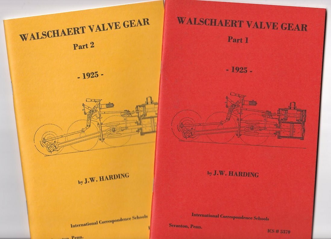
Walschaert Valve Gear (Part 2) Details of Gear, ICS #, originally published International Correspondence Schools, Scranton, Pennsylvania, 1925. Reprinted by Nation Builder Books, Mebane, NC, 2015. 5½ x 8½ photocopied booklet, 60 pages.
Please note these are new photoduplicated reproductions, not originals. The accompanying pictures were scanned from reprints, not the originals.
If you are a live steamer, and you’ve always wanted to know the two general methods of connecting a radius rod to a reverse-shaft crank, then these are the books for you. (We also have the ICS booklets on the Stephenson valve gear and Baker valve gear). This book will explain why a different type of gear frame must be used for a two-wheel engine truck, than for a four-wheel truck. Or what change in position is brought about by the movement of the reverse lever. And why the Stephenson valve gear can be used only on the early steam locomotives.
And if you’re lucky and skilled enough to actually operate a live steam locomotive or engine, at a threshermen’s reunion or antique tractor show for example, then maybe you’ve pondered what to do if a link hanger or radius rod breaks. And wouldn’t it be cool to be able to explain to all those bystanders what an eccentric does, and how an engine is put into reverse?
As is usual with most correspondence course booklets by the International Correspondence Schools, this is richly illustrated with crisp line drawings.
Contents, Part 1, Arrangement and Operation: Action of Gear
- Introduction
- Principles Underlying Gear
- Characteristics of Walschaert Gear
- Investigation of Principles
- Position of Valve With Respect to Piston
- Position of Valve With Respect to Main Crank
- Operation
- Gear Not Reversible
- Arrangement for Reversing
- Effect of Lap and Lead on Arrangement
- Arrangement for Moving Lap and Lead
- Effect of Combined Motions
- General Description
- Views of Valve Gear
- Name of Parts
- General Arrangement of Parts
- General Operation
- Movement Imparted by Reverse Lever
- General Operation of Gear
- Oiling Points in Valve Gear
- Eccentric-Crank and Combination-Lever Movement
- Combination of Movement
- Separation of Movement
- Movement Imparted by Eccentric-Crank
- Movement Imparted by Combination-Lever
- Location of Radius-Rod Connection With Outside- and Inside-Admission Valves
- Different Arrangements of Gear
- Types of Gear Frames
- Reason for Different Types
- Types of Radius-Rod Hangers
- Types of Reverse-Shaft Cranks
- Arrangement of Crank
- Disadvantages
- Difference in Thrust on Link-Trunnion Bearings
- Link-Block Slip
- Eccentric Crank
- Development of Eccentric Crank
- Action of Eccentric Crank
- Position of Eccentric Crank
- Direct and Indirect Motion
- Center Line of Motion
- Conditions on Which Positions Depends
- Outside-Admission Valve and Direct Motion
- Inside-Admission Valve and Direct Motion
- Link Arc and Link Radius
- Constant Lead
- Curvature of Link With Walschaert and Stephenson Gears
- Variable Preadmission with Constant Lead
- Examination Questions
Contents, Part 2, Details of Gear
- Gear Frame
- Purpose
- Reason for Different Types
- Construction
- Cross-Ties and Guide Yokes
- Purpose
- Decription
- Eccentric Crank
- Purpose
- Construction
- Applying and Removing Eccentric Crank
- Eccentric Rod
- Purpose
- Construction
- Purpose and Construction of Link
- Purpose
- Construction
- One-Piece Link
- Dimensions of Link
- Radius Rod
- Purpose and Construction
- Assembly of Link, Link Block, and Radius Rod
- Combination Lever
- Purpose
- Construction
- Proportions of Combination Lever
- Rule
- Combination, or Union, Link
- Purpose
- Construction
- Radius-Rod Hanger
- Purpose
- Construction
- Radius-Rod Hanger-Pin
- Reverse-Shaft Crank and Reverse-Shaft Arm
- Purpose
- Construction
- Reverse Shaft
- Purpose
- Assembly of Parts
- Assembling Link
- Assembling Radius Rod in Link
- Assembling Radius Rod Lifter
- Arrangement and Assembly of Combination Lever and Valve-Stem Crosshead
- Other Arrangements of Combination Valve-Stem Crosshead and Guides
- Arrangement of Valve-Stem Crosshead and Guide With Outside-Admission Valve
- Reversing
- General Explanation
- Principle Involved
- Movement of Valves When Reversing
- Change in Cut-Off
- General Explanation
- Principle Involved
- Back-Set of Link Foot
- Angularity of Eccentric Rod
- Effect of Back-Setting Link Foot
- Breakdown
- Obtaining Gear Movement When Gear Fails
- Broken Eccentric Crank, Eccentric Rod, or Link Foot
- Broken Radius Rod
- Broken Combination Lever or Union Link
- Broken Lift Hanger or Lift-Hanger Pins
- Examination Questions